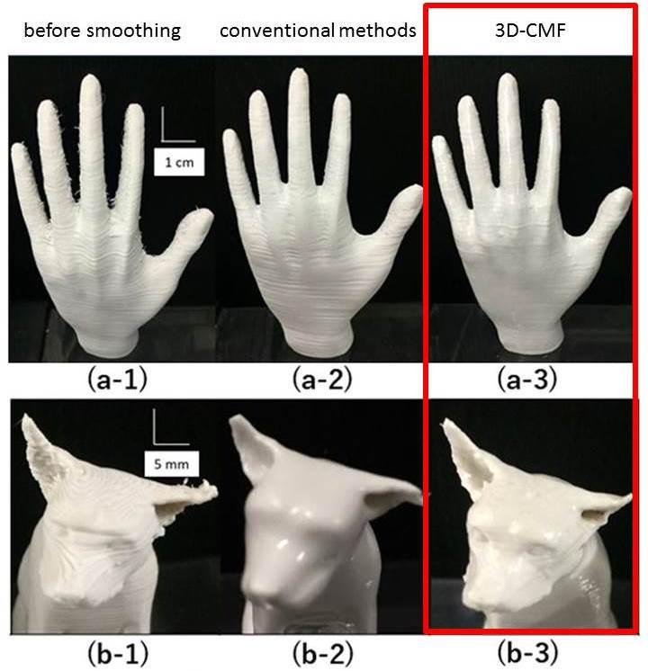
Visible layer lines and a prominent Z-seam are among the most common visual challenges in FDM 3D printing. Although they can never be completely eliminated for technical reasons, they can be significantly reduced through targeted settings – for a cleaner surface and more professional parts.
1. Layer Lines in 3D Printing – Understanding the Causes
Why do visible layer lines occur?
In FDM printing, the object is built up layer by layer. Each layer is minimally visible – especially with larger layer heights or unfavourable print parameters.
Typical causes:
- High layer height
- Fluctuating extrusion
- Uneven cooling
- Mechanical vibrations
- Unstable Z-axis
2. Reducing Layer Lines – The Most Important Adjustments
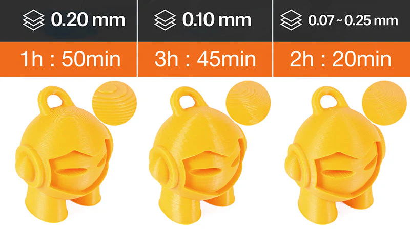
🔹 Optimise layer height
Rule of thumb:
- For fine surfaces → 0.1–0.16 mm
- Standard quality → 0.2 mm
- Fast printing → 0.24–0.3 mm
The smaller the layer height, the smoother the surface – but print time increases.
🔹 Fine-tune print temperature
Too high temperatures lead to:
- blurred details
- slightly "melted" appearance
Too low temperatures cause:
- poor layer adhesion
- visible transitions
👉 Test temperature in 5 °C steps.
🔹 Optimise cooling
Even part cooling ensures clean layers.
- PLA → high cooling (80–100 %)
- PETG → moderate (30–60 %)
- ABS → low (0–30 %)
Irregular cooling can cause banding.
🔹 Check mechanics
Layer banding or recurring stripes can be caused by mechanical issues:
- Dirty or dry guides
- Out-of-round lead screws
- Loose belts
- Play in the Z-axis
Regular maintenance significantly improves print quality.
3. Z-Seam in 3D Printing – What Is It?
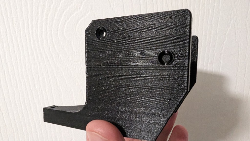
The Z-seam occurs where each new layer begins and ends. At this point, a small amount of excess material can accumulate – visible as a fine line or row of points along the part wall.
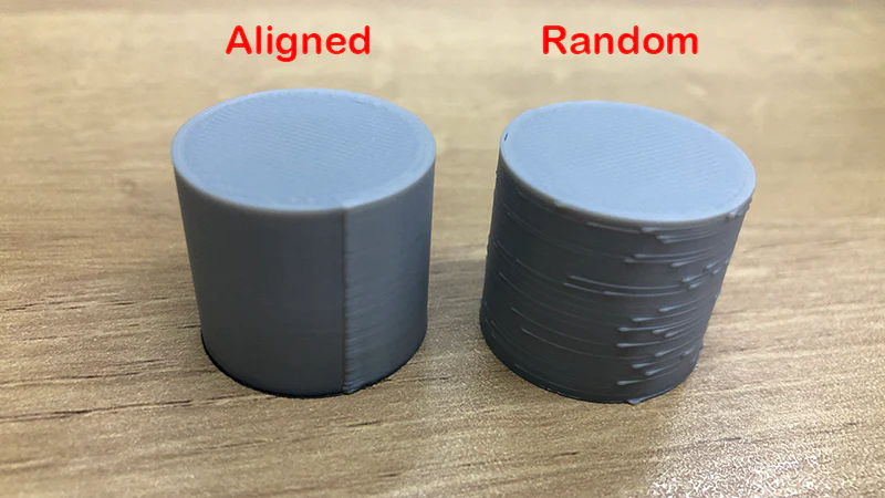
4. Controlling the Z-Seam
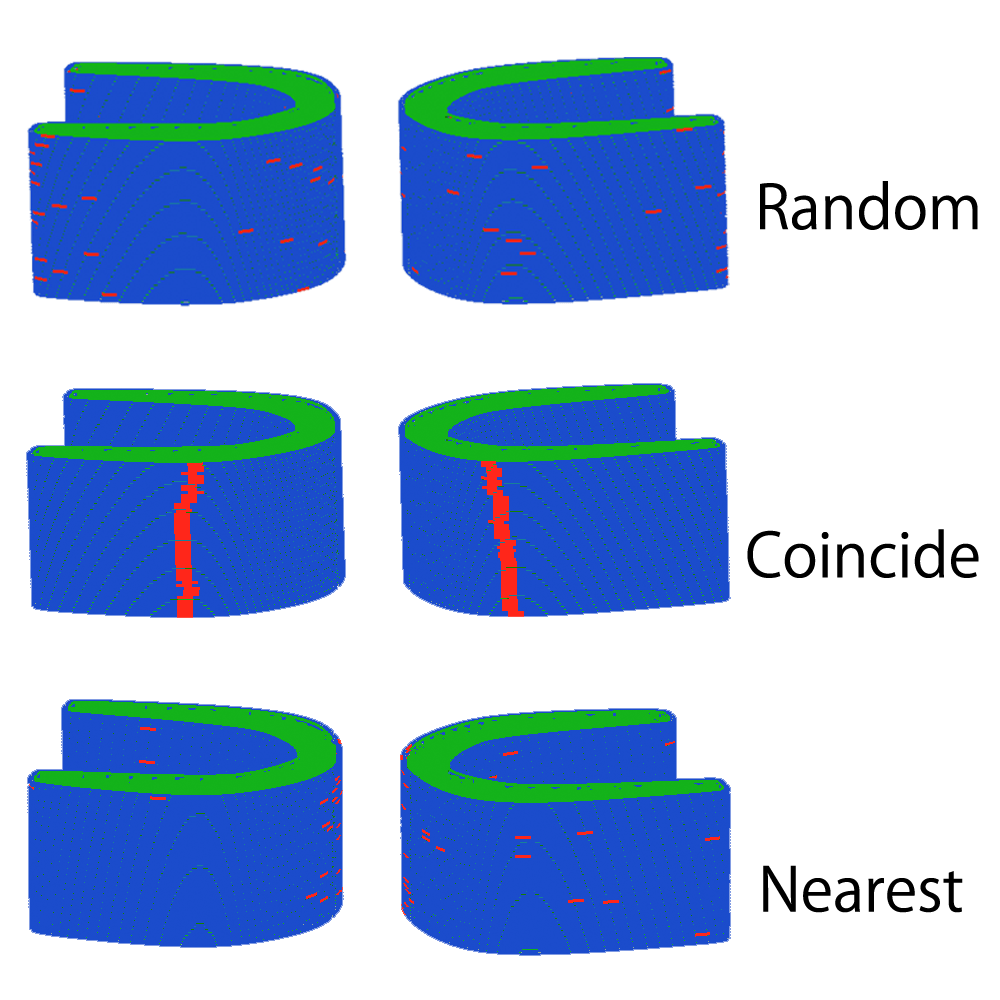
🔹 Set seam position in the slicer
Most slicers offer options such as:
- "Aligned" → Seam at a fixed position
- "Rear" → Seam on the back
- "Random" → Evenly distributed
Tip: For functional parts, place the seam on an edge. For round objects, choose "Aligned" or "Rear".
🔹 Enable coasting & wipe
These functions reduce material pressure before the layer change:
- Coasting → Stops extrusion slightly earlier
- Wipe → Wipes off excess material
Especially helpful with PETG.
🔹 Use Linear Advance / Pressure Advance
Modern firmware features (e.g. in Klipper or Marlin) regulate material pressure in the hotend more precisely and significantly reduce blobs at the Z-seam.
5. Improving Overall Surface Quality
🔹 Reduce print speed
Slower printing = more even layers. Outer walls in particular should be printed slower than infill.
🔹 Print outer walls last
Many slicers offer the "Outer walls last" option. This ensures clean outer surfaces without visible infill marks.
🔹 Use more perimeters
More outer walls (e.g. 3 instead of 2) improve:
- Stability
- Appearance
- Surface uniformity
6. Post-Processing for Perfect Surfaces
If layer lines are visually distracting:
- Sanding (grit 200–1000)
- Filler & painting
- Acetone smoothing for ABS
- Epoxy coating
For technical parts this is often unnecessary – for design objects it makes sense.
Pro Checklist for Smooth Surfaces
- ✔ Choose appropriate layer height
- ✔ Set temperature optimally
- ✔ Use cooling appropriately for the material
- ✔ Maintain mechanics regularly
- ✔ Place Z-seam consciously
- ✔ Print outer walls slower
Conclusion
Layer lines and Z-seam are natural side effects of FDM 3D printing – but not a quality defect when controlled. With targeted slicer settings, clean mechanics and material-appropriate cooling, surfaces can be significantly improved.
Those who optimise systematically will achieve visibly more professional print results.